Objectives

The objective of this project is that I want to design the relay board that can be used for IoT purpose. I aim to combine the ESP32 Wroom 32D and 4 relays into a single board as well as the micro USB programmer on board for the ESP32.
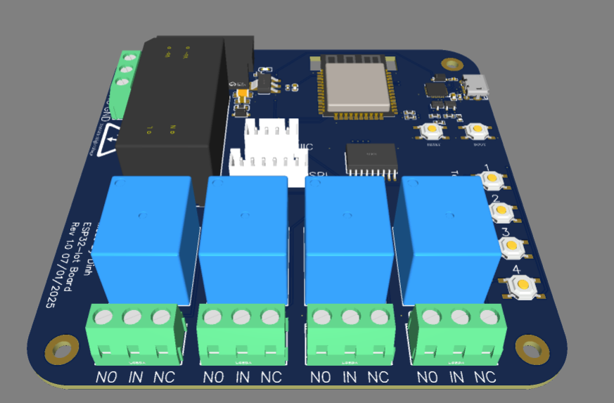
Design features

  • The board consist of a AC-DC converter module, which take the 220V AC input and convert to 5V for powering the MCU and triggering relays. The efficiency of the power isn't need to be really high, as we don't need to power any device that require high current. So we can use the one from Hi-Link (HLK-2M05), that have the efficiency around 69%. Additionally, there is a 1A fuse for the saftety.
  • There are 2 groves for I2C and SPI connect to the board. For example, an OLED screen or any sensors.
  • Board layout

  • In order to control 4 relays, I used a ULN2803ADWR. The ULN2803ADWR is often needed to control relays with a microcontroller like the ESP32 because it acts as an interface between the low-current, low-voltage digital output of the ESP32 and the higher-current, higher-voltage requirements of relays. Moreover, the ESP32 might not have enough current to drive the relays, and it could be damaged by back-EMF. The ULN2803ADWR ensures reliable relay control while protecting the microcontroller and simplifying the circuit
  • There are also high voltage gap for the relays.
  • There are 4 switches used for testing purpose, if the application required any button to trigger or pressing to set up the parameters.
  • Schematic