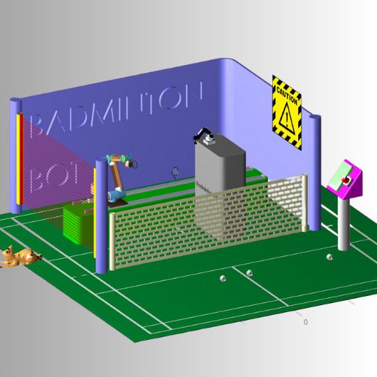
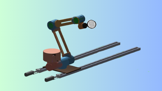
A simulation model of 7 DOF robot arm mounted on linear rail playing badminton
Objectives
This is one of the assignments in the subject 41013 Industrial Robotics that I am really proud of sharing with everyone. The requirements for this project are:
Why did I choose a redundant 7 DOF robot?
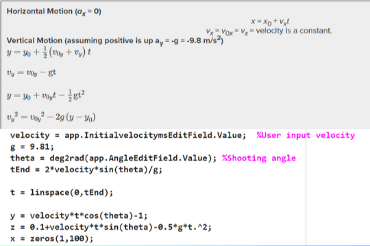
Motion of the shuttlecock
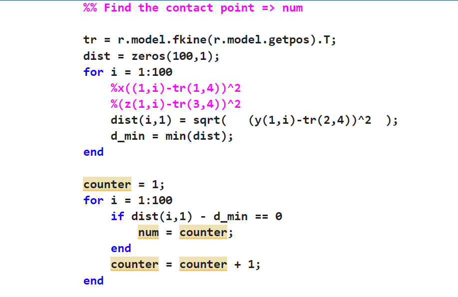
Where should it hit?
- Firstly, I find the position of the endeffector by taking the forward kinematic with the function fkine()
- Then, I create a zeros matrix of 100x1 for storing the distance.
- I take the distance in the Y direction of the endeffector to each point on the trajectory of the shuttlecock that I have already predicted before.
- Then I find the mininum this distance of it and which point will give the least distance.
Image Based Visual Seroving
I also integrate the visual servoing for the robot, this method call image based visual servoing, this means the camera mounted on the endeffector and we can map the velocity of the image pixel to the velocity of the endeffector by multiply the image Jacobian matrix to the velocity of the endeffector. The video on the right demonstrates how the image based visual seroving work, I mount a camera on the endeffector but I make it invisible, the desired frame is that camera will be at the center of the opponent racket at 500x500px.
Final video demonstration
This is the final video demonstration for the system, it can demonstrate better how I apply the RMRC and path planning between poses. The method that I used to detect the collision is ellipsoid check, it means creating an ellipsoid around the links of the robot and check the distance between the points and the radius of the ellipsoid to see if it lie on the surface or inside or outside the surface. RMRC is integrated in generating the hitting trajectory of the shuttlecock, after finding the hitting point, racket will move backward a bit just like when we swing the racket to have more inertia, and then it will move in a straight line with RMRC to move to the hitting point. All the poses are generated with inverse kinematic to find the joint states for the robot. All the code can be found on my GitHub.