
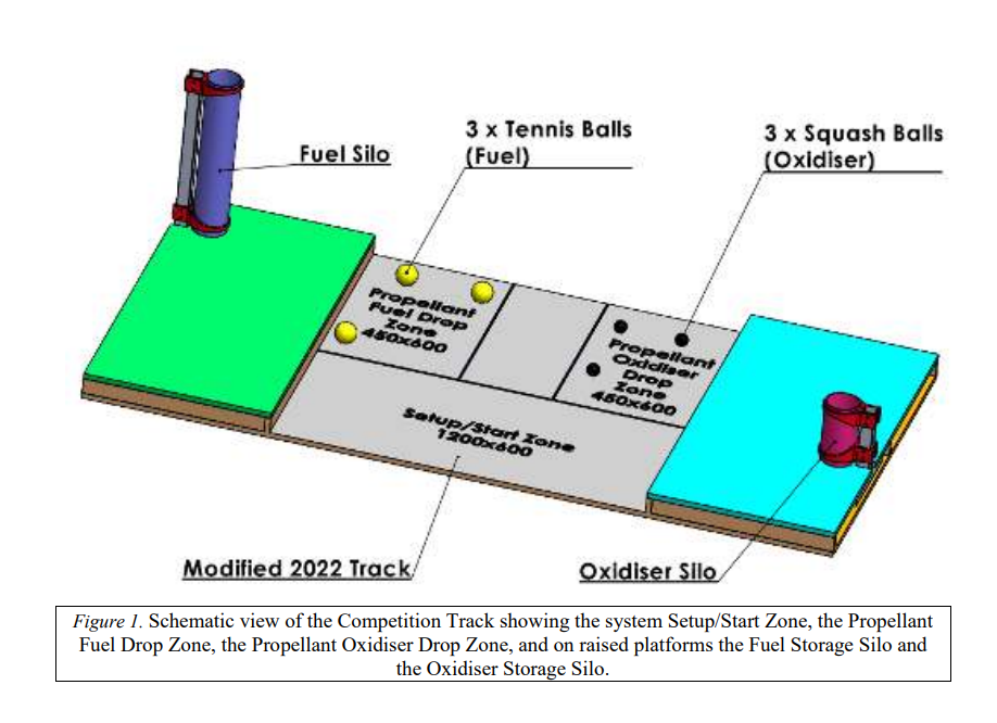
Design a robot working autonomously delivering the payloads to the respective silos
Objectives
The Warman Competition 2023 is part of the subject that I take in the Spring semester 2023 call 41059- Mechanical Fundamental Design Studio. The main objectives for this project are as follows:
Solution proposal
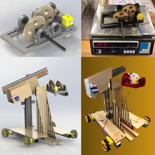
Gearbox
Why a gearbox... We target to the make the robot with lowest budget and the most weight efficient for the component. There are many ways to generatet the rotational movement for the scoop such as servo or stepper motor or a dc motor. However, a servo that can generate a sufficient torque with 350mm lever arm is so expensive for our budget, that is also the reason for rejecting using the stepper motor and the gear dc motor.
In order to design this gearbox, I applied the following knowledge:
Result
This is the video that I tested the gearbox and my scoop. As you can see, in the video the gear are 3D printed with red PLA filament not wood material just like in the CAD model. Previously, I have not bought the 3D printer yet so I need to use the 3mm plywood that I can use this free in the Mechatronics lab in the university, to create the 9mm thickness I have to cut 3 pieces of plywood and glue them together. However, there was a problem with the precision of doing that, all the gears were not straightly aligned, I just doing that for submitting my own artifact for my assignment, after that the printer arrived I decided to print all the gears again.
Code integration
Conclusion
After this 12-week project, I have acquired many invaluable knowledge and skill: